No products in the cart.




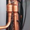
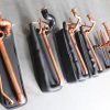
ERP A+++ CE WIFI Water Heating Cooling EVI DC Air Source Heater Pump r290 monobloc Geyser HVAC -35deg water heater heat pump
ADC-32H
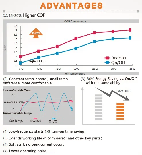
- 5 years warranty
- SG ready function
- Energy class A+++ / A++
- Quiet operation up to 58 dB
- Application for remote control of the pump for Android or iOS
- Water outlet temperature up to 60 degrees
- R32(high performance and low environmental impact)
Quote Now
Product Features
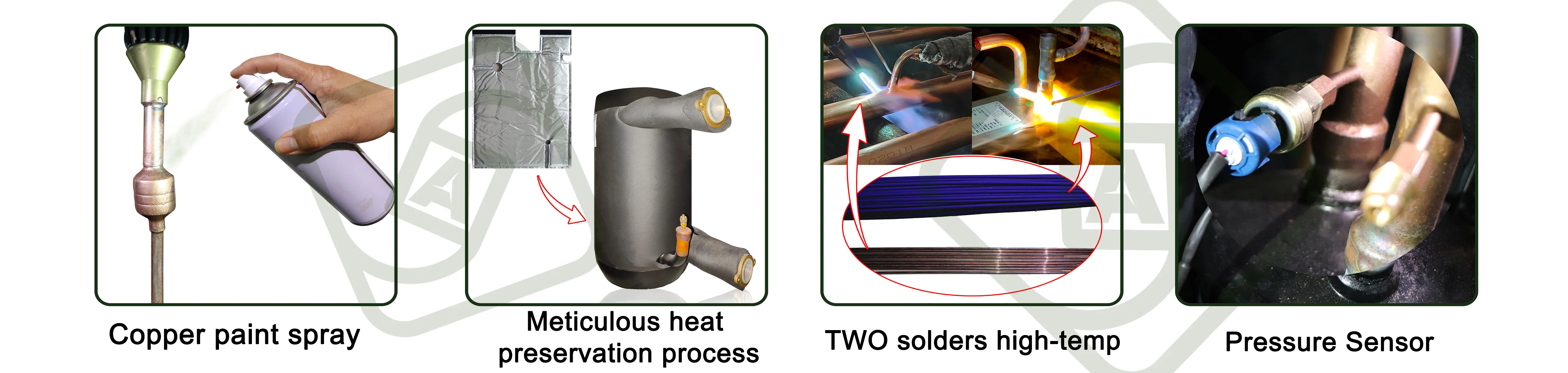
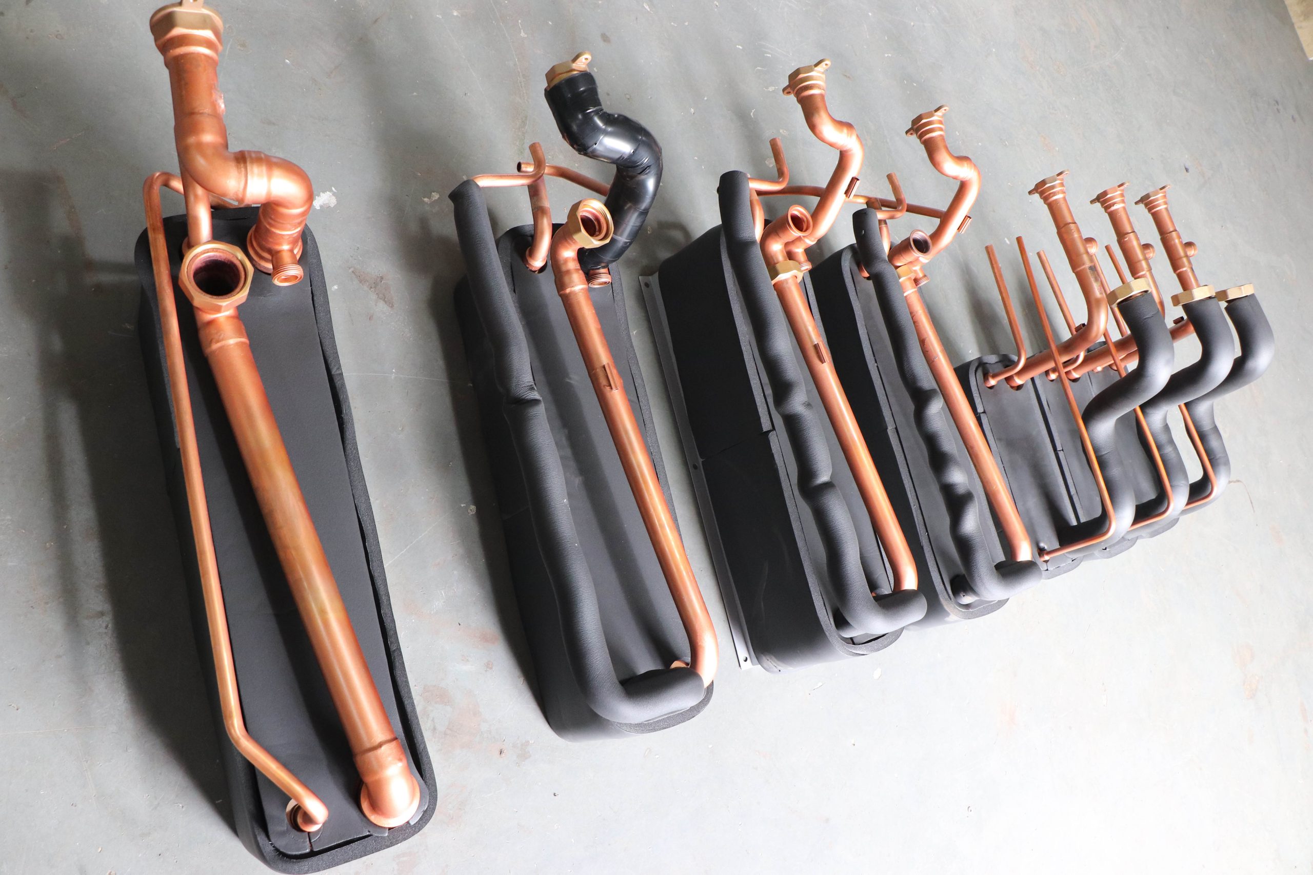
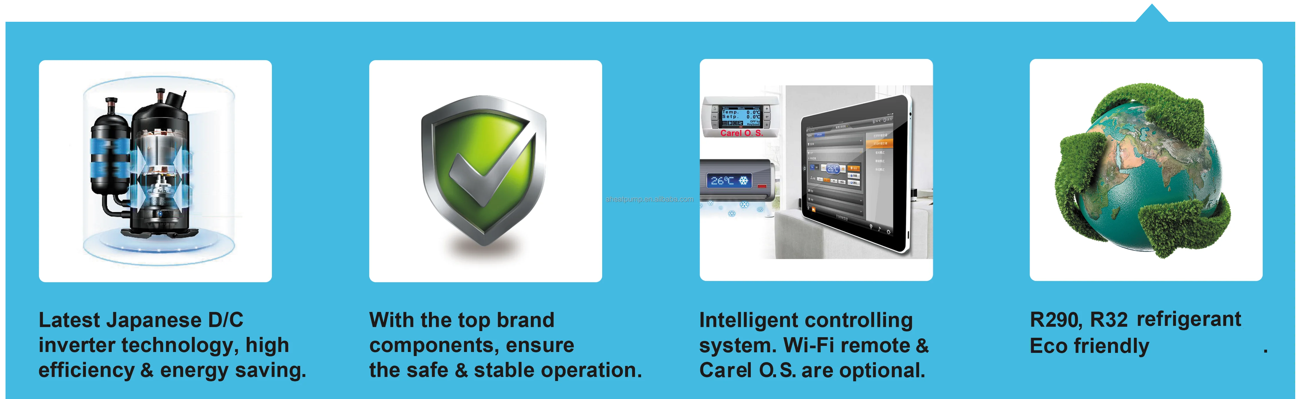
1.Copper paint spray sealing on welding port/soldering point surface, highly anti-rusting & deeply balancing uneven tension by poor welding.
2.Meticulous heat preservation process. High-quality thermal insulation tape combines with high-density Polyeaster rubber-plastic thermal insulation foam, conducting 360°thermal insulation around components & pipes, heat loss in 24H is <4℃ & seals much noise.
3.TWO solders high-temp. welding, fully improving welds’ strength to reduce gas leakage. Mysteriouse flux miraculously improves auxiliary heat conduction, removing oxides, reducing welded surface tension & increasing the area, preventing re-oxidation &>2-time prolonging pipeline’s life.
4.”Pressure Sensor” takes place of Pressure Gauge, not easy to frost, with “pressure”, “water flow” & more real-time data can indicates in LED screen.
Parameter

| Model | ADC-26H | ADC-32H | ADC-40H | ||
| HP | 8HP | 10HP | 12HP | ||
| Power Supply | 380-415V/50-60Hz/3ph | ||||
| Heating Condition: Ambient Temp. +7℃/+6℃(WB/DB), Water Temp. +30℃/+35℃(In/Out). | |||||
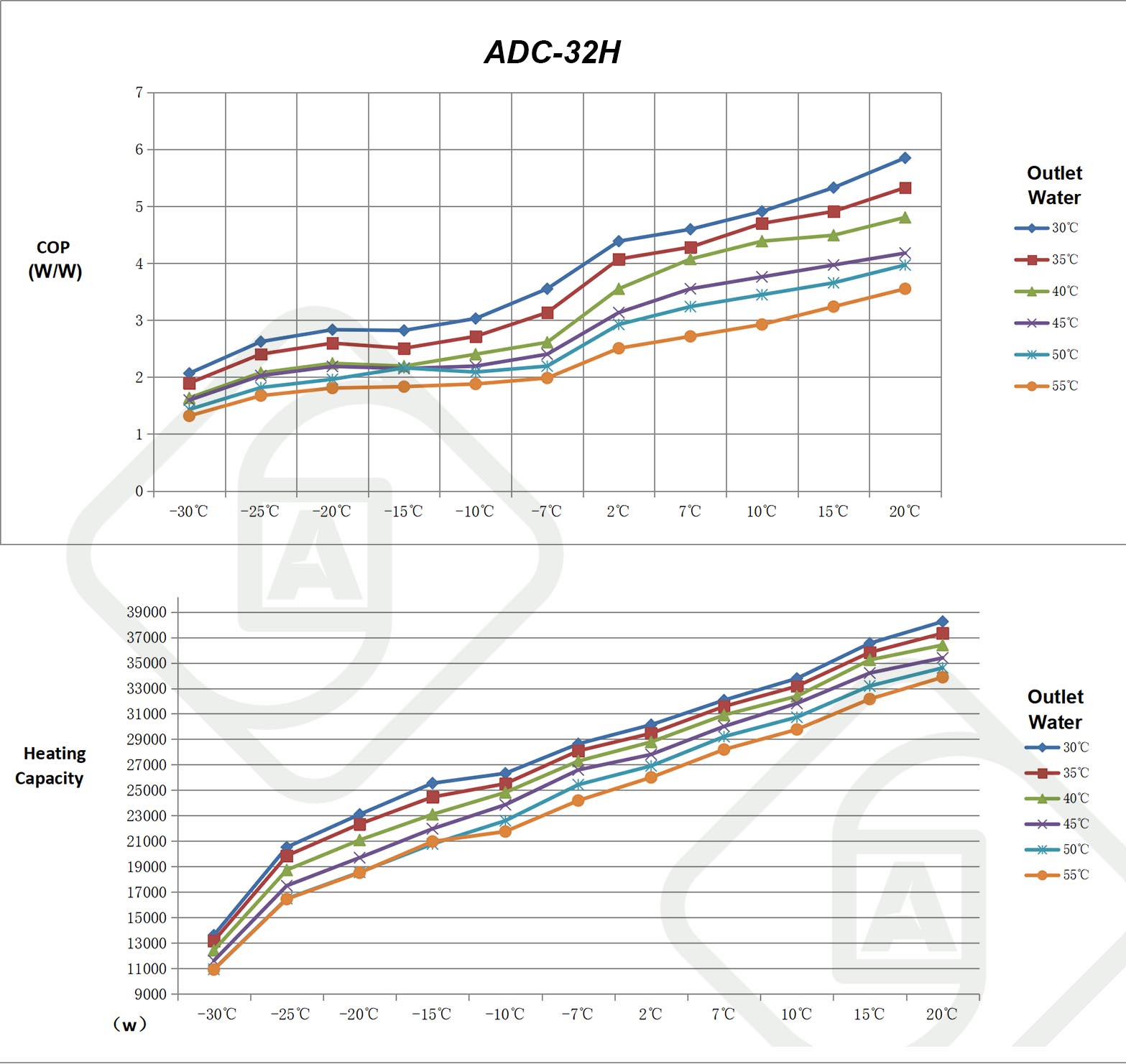
| Heating Capacity Rang | kW | 6.43-21.57 | 7.96-26.98 | 11.54-33.16 | |
| Power Input Range | kW | 1.04-4.85 | 1.27-5.96 | 1.76-7.27 | |
| Hot Water Condition: Ambient Temp. +20℃/+15℃ (DB/WB), Water Temp. +15℃/+55℃ (In/Out). | |||||
| Heating Capacity Rang | kW | 6.97-25.95 | 8.75-32.45 | 11.66-39.68 | |
| Power Input Range | kW | 1.44-5.45 | 1.75-7.76 | 2.37-9.43 | |
| SCOP | at 35℃ water outlet | 4.85 | 4.86 | 4.84 | |
| at 55℃ water outlet | 3.54 | 3.50 | 3.53 | ||
| ErP Level | at 35℃ water outlet | A+++ | A+++ | A+++ | |
| at 55℃ water outlet | A++ | A++ | A++ | ||
| Heating operation range | Ambient | °C | -30~25 | ||
| Heating side | °C | 18~60 | |||
| Domestic hot water operation range | Ambient | °C | -30 ~ 43 | ||
| Water side | °C | 25~60 | |||
| Chilling Condition: Ambient Temp.35℃/30℃ (DB/WB), Water Temp.12℃/7℃(In/Out). | |||||
| Chilling capacity | kW | 4.83-18.56 | 6.68-23.73 | 9.28-29.86 | |
| Power input range | kW | 1.65-6.23 | 1.93-8.34 | 2.42-10.05 | |
| Chilling operation range | Ambient | °C | 10~43 | ||
| Water side | °C | 7~22 | |||
| Rated water flow rate | m³/h | 2.95 | 3.5 | 3.8 | |
| Rated pressure drop | kPa | 47 | 47 | 49 | |
| Max. working pressure | Refrigerant | Bar | 44 | 44 | 44 |
| Water | Bar | 7 | 7 | 7 | |
| Controller | Micro processor based digital wire controller, LED Touch Screen | ||||
| External cabinet | Galvanized steel with powder coating | ||||
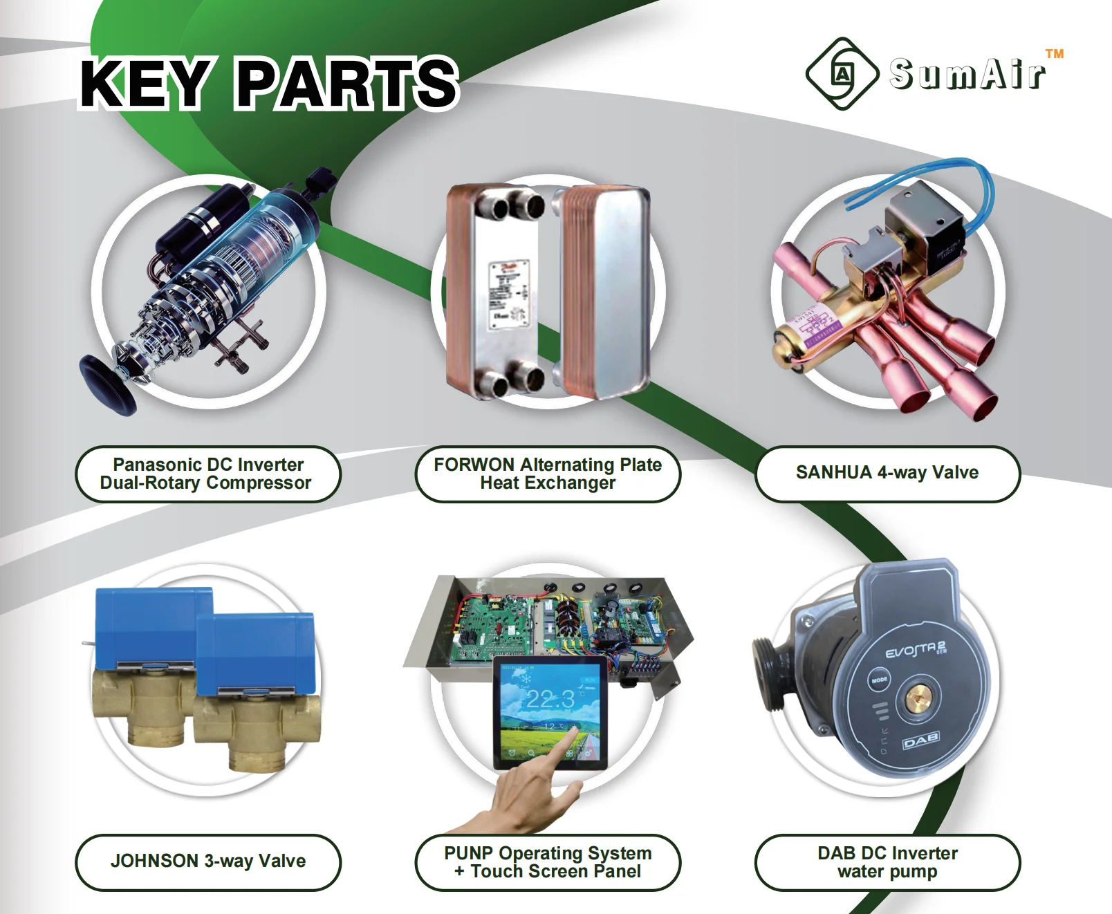
| Compressor | Type | Panasonic Dual Rotary | |||
| Refrigerant | R32 | ||||
| Water heat exchanger | SUS 316 Brazed plate heat exchanger | ||||
Detailed image

Working Principle
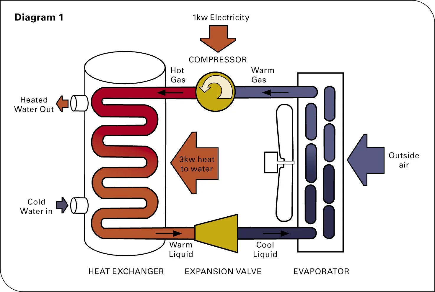
1. In the heat pump, the evaporator coil is exposed to the outside air.
2. The refrigerant enters the evaporator as a cold liquid/gas mixture at low pressure.
3. Heat from the outside air causes the refrigerant to boil into gas.
4. This gas is pumped through to the condenser coiI by a compressor which also increases the refrigerant’s temperature and pressure.
5. The refrigerant is now hotter than the temperature of the water in the tank, so heat flows out, heating up the water in thetank and condensing the refrigerant back into a liquid.
6. The refrigerant then flows through an expansion valve that allows the pressure and temperature to drop again by the time it reaches the evaporator coil.
7. Once the refrigerant reaches the evaporator coil the cycle is repeated.
SG ready
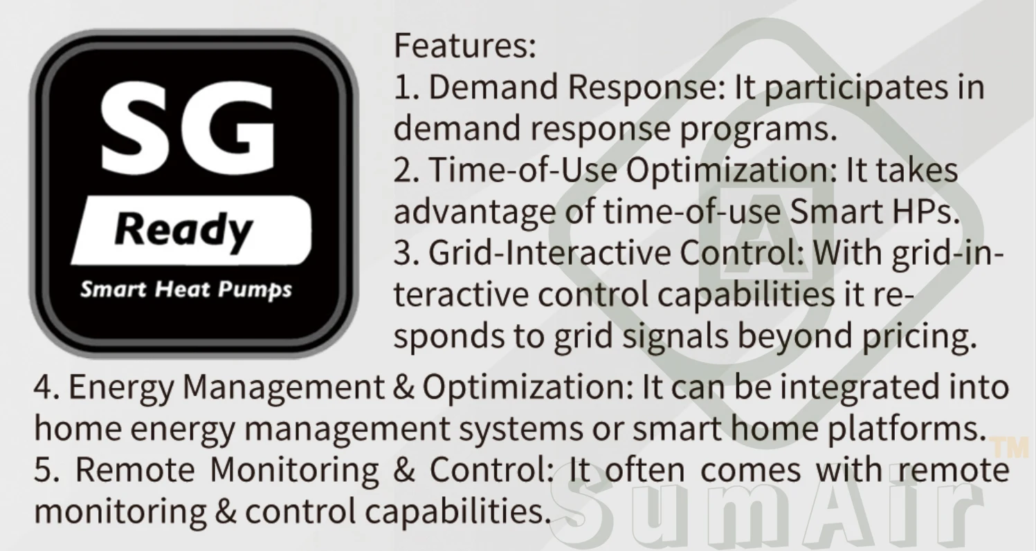
SG ready Control logic
When Smart Grid Function is set to “Use”, the logic is as follows:
SG Grid Signal [LDIsg] | EVU Supply Signal [LDIevu] | Smart Grid Command | Smart Grid Display |
0 | 1 | Smart Grid Directive 1 | Display low-peak power consumption icon |
0 | 0 | Smart Grid Directive 2 | Display peak power icon |
1 | 0 | Smart Grid Directive 3 | Indicates free electricity icon |
1 | 1 | Smart Grid Directive 4 | Indicates free electricity icon |
There 4 state of the smart grid of our system control, if you want to know more details, please feel free to contact me!!!
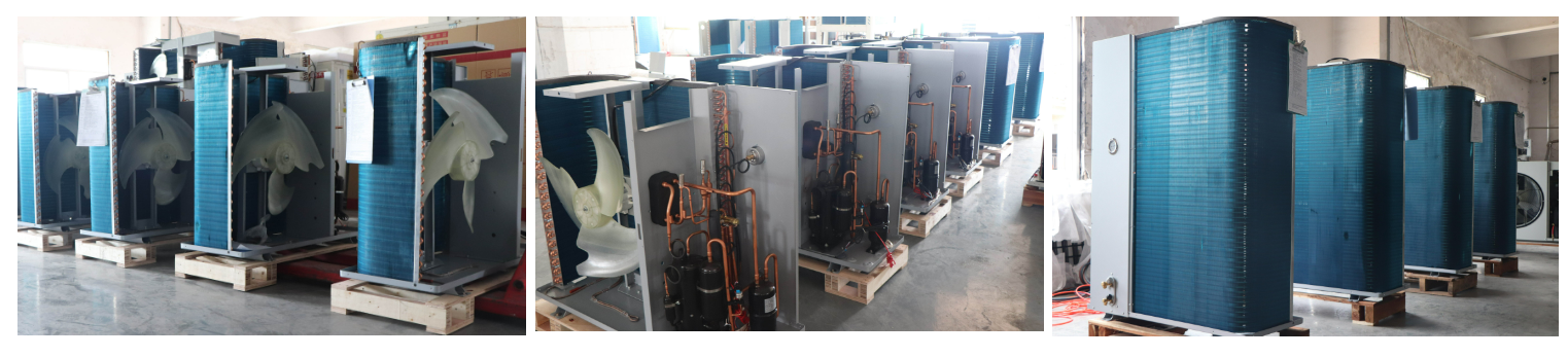
Products in Line
Packages

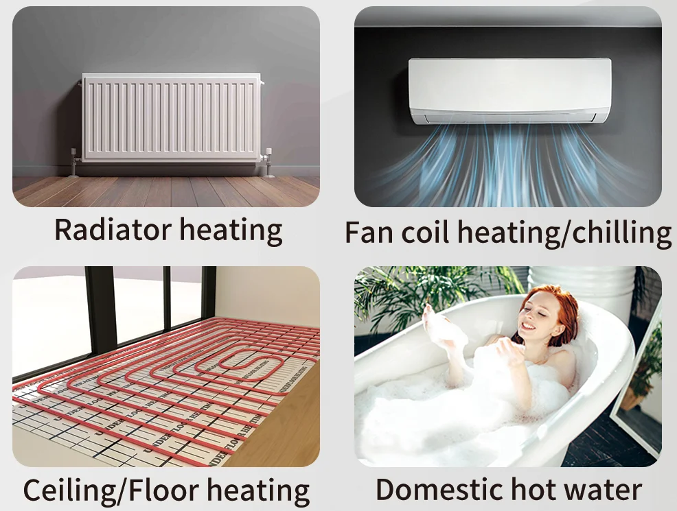
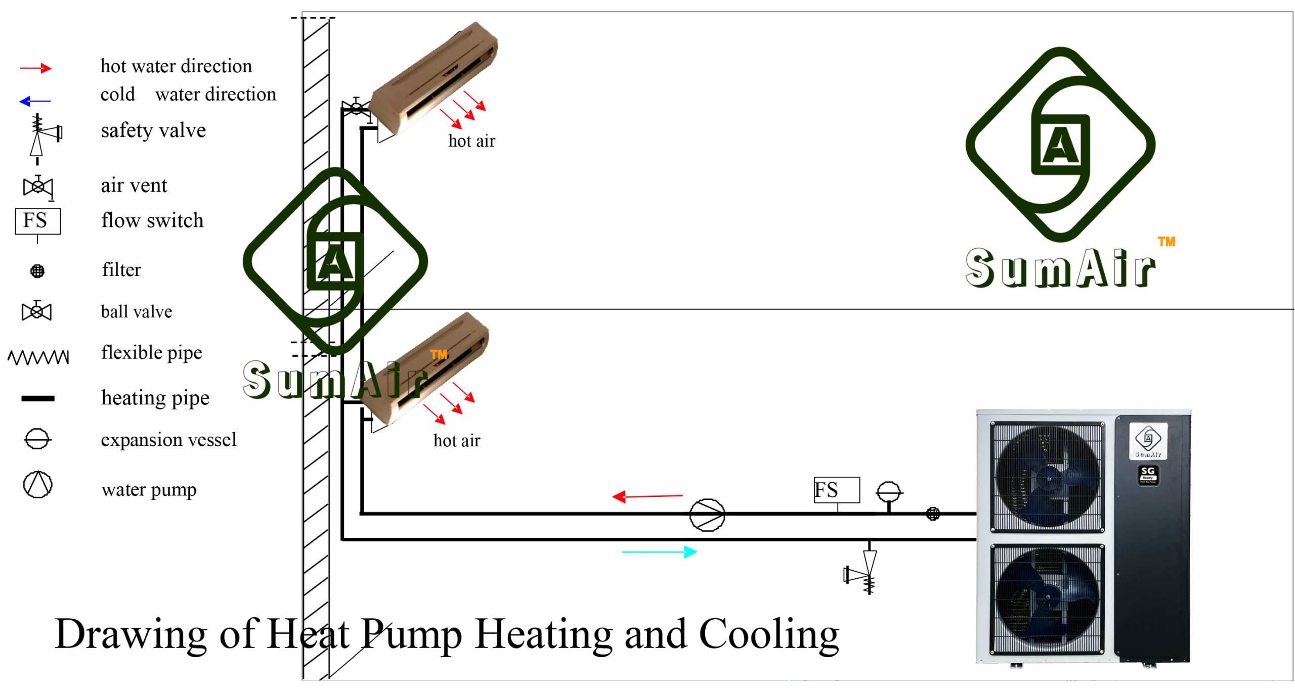
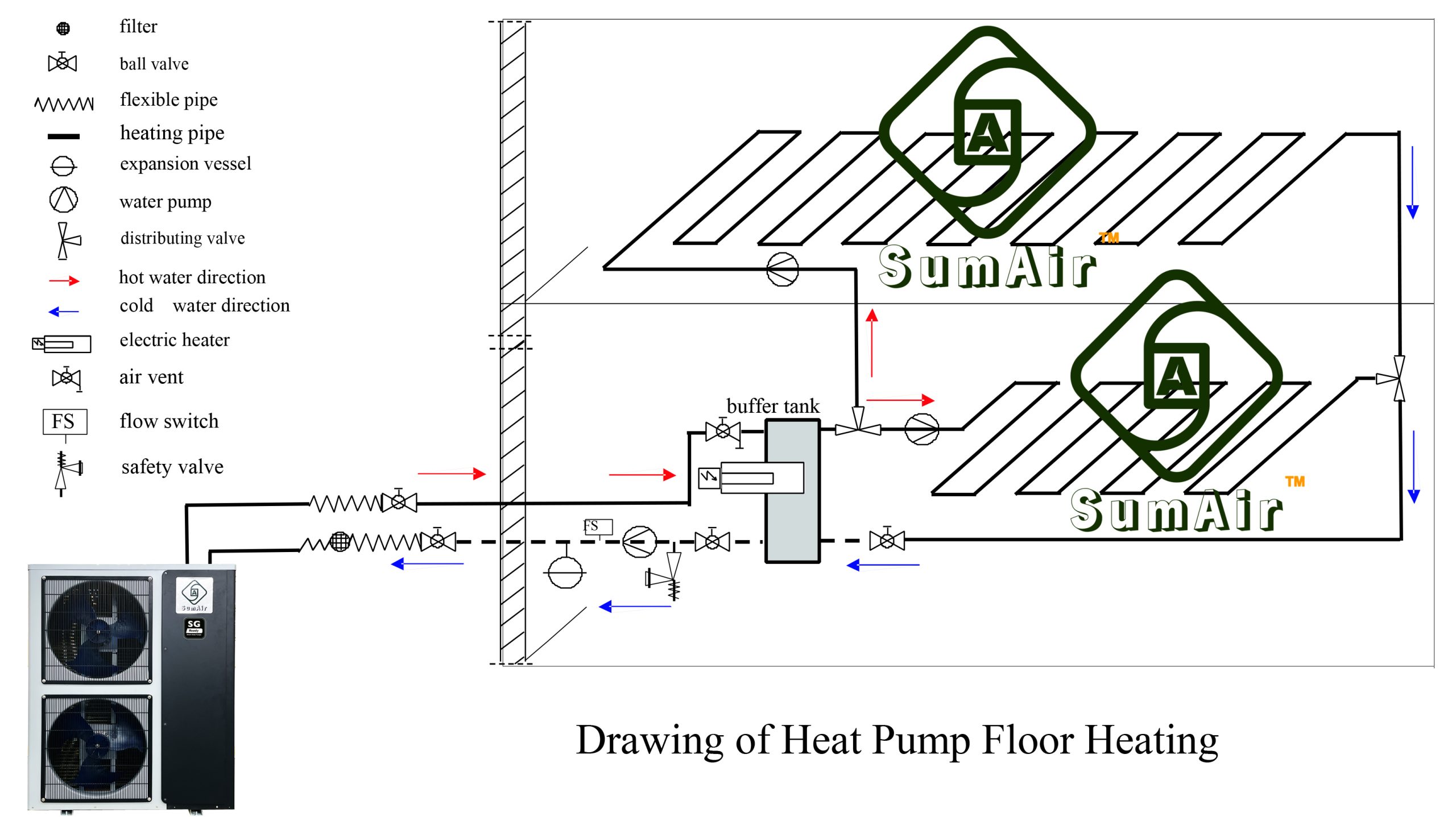
Applications & Install Reference